Analog signals transmitted through long wires can pick up a lot of noise – the wire will act as an antenna. High frequency noise can be filtered with a lowpass filter. I’ll design, implement, and test an RC filter.
Following the posts about Botanix and Effectively killing a plant the project will use an analog soil moisture sensor. As the Raspberry Pi only has digital inputs conversion is needed – enter MCP3008.
An Analog to Digital Converter (ADC), as the name suggests, converts analog signals – current levels – into digital values. The MCP3008 converts current levels from 0v to 3v into corresponding digital values of 0 to 1024.
This noise will be of a much higher frequency than the signals we are trying to read – in this system at least. As mentioned this can be filtered using a lowpass filter implemented as an RC filter. However, it is a good idea to determine if the problem is actually there, before solving it.
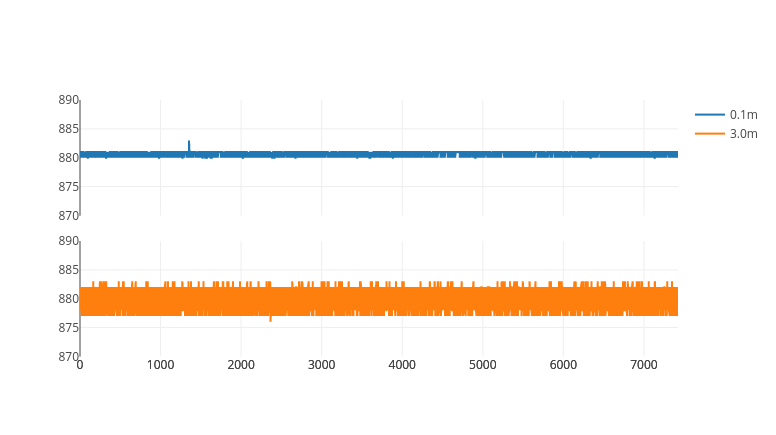
I estimated that the longest I will need to run wires for will be 3 meters. So, I took two capacitive soil moisture sensors and connected them to the ADC – one with about 0.1 meter of wire and the other with about 3 meter of wire. I placed them next to each other on a table and connected data for an hour – the results are seen in the plot at the top.
More noise is definitely present and a filter is probably a good idea. One approach could be to sample multiple times and do a mean value calculation in software. But as the sole purpose of this project is for me to learn, I’ll do a hardware filter – an RC Filter.
RC Filter
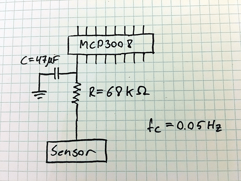
The RC filter consists of a resistor (R) and a capacitor (C) and is hence called RC. It is a low pass filter which allows signals of low frequency (slowly changing signals) to pass through while filtering out high frequency signals. The cut off frequency (fc) determines which frequencies pass and which are filtered out. The cut off frequency is configured by the values of R and C.
In my setup I am only interested in low frequency signals and thus aimed for a cut off frequency of 0.05Hz. I used an online tool to determine my R and C values: www.learningaboutelectronics.com
After implementing the filter I repeated the test from above and the effect of the filter is evident.
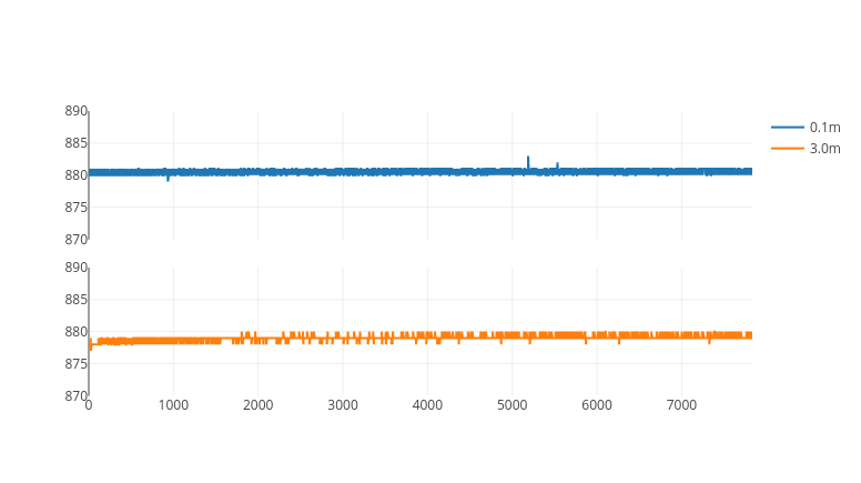
The filter does however have an impact on the reaction time of the sensor. I expect the drying out of soil to be quite slow so for these measurements there will be no problem. But what about when I water the plant? I that case I would want to get an idea if enough water has been added quite quickly. But before redesigning the RC filter for a faster response time lets first do some testing.
I have two sensors wired up. One which is directly connected and one that has the RC filter implemented. Both sensors are dry at the beginning of the test and the put in a glass of water at the same time. An added bonus of this test is that the dynamic range of the sensor is determined, which we need to know in the software if we want to relate measurements to something human readable.
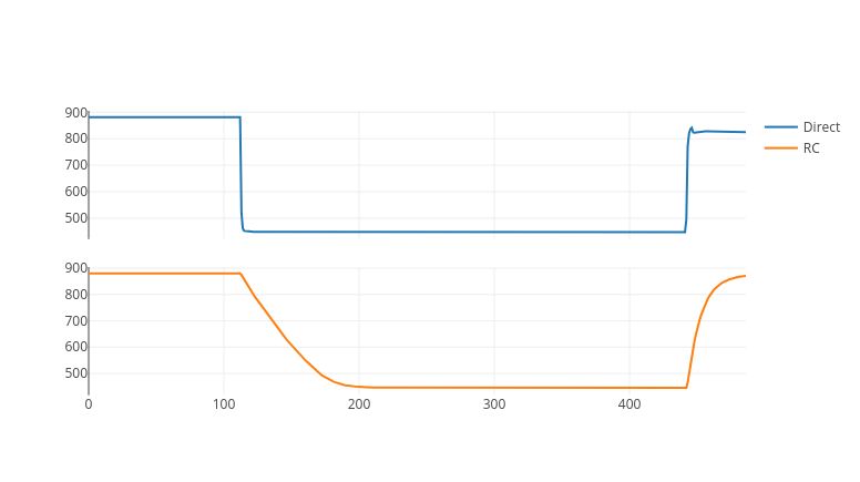
The count on the x-axis is number of samples at a sample rate of 2Hz. So 100 samples equals 50 seconds. 60 seconds of settle time is enough and is acceptable in my design.
The dynamic range of the sensor goes from 890 for completely dry to 450 for completely wet.