 The first sensor array will consist of an ESP8266 with a BME280 and a CCS811. As I described in AirPatrol the upstairs sensor array, called Chase, is a downscaled version of Marshall for added monitoring. It is the simplest of my three sensor arrays with fewest sensors. Therefore, it is also ideal as my first build.
Materials
Below are lists of materials and tools I used for the build. First a few words on my choise of the main components.
I don’t need the added capabilities of the ESP32 so the ESP8266 is chosen as the main board.
The BME280 I selected over the more popular DHT11 and DHT22 sensors as it has a better reputation regarding lifetime in humid environments. Additionally, the BME280 offers temperature, humidity, and pressure readings whereas the DHT22 only offers temperature and humidity.
The CCS811 should be able to measure Total Volatile Organic Compounds (TVOC) and estimated CO2 levels. And I already had it on stock.
Materials:
- ESP8266 Main board.
- BME280 Temperature, Humidity, and Barometer sensor.
- CCS811 TVOC sensor.
- 5V Power Supply.
- Plastic box.
- Wires.
- Heat shrink tube.
Tools:
- Wire cutters.
- Soldering iron.
- Hot glue gun.
Optional:
Design
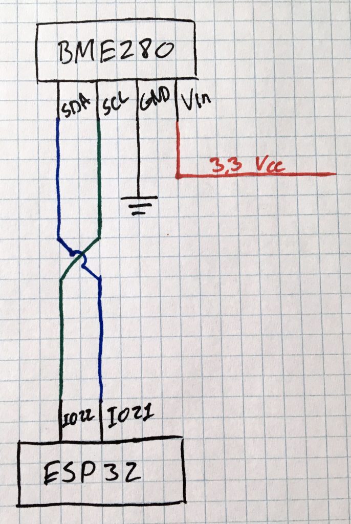
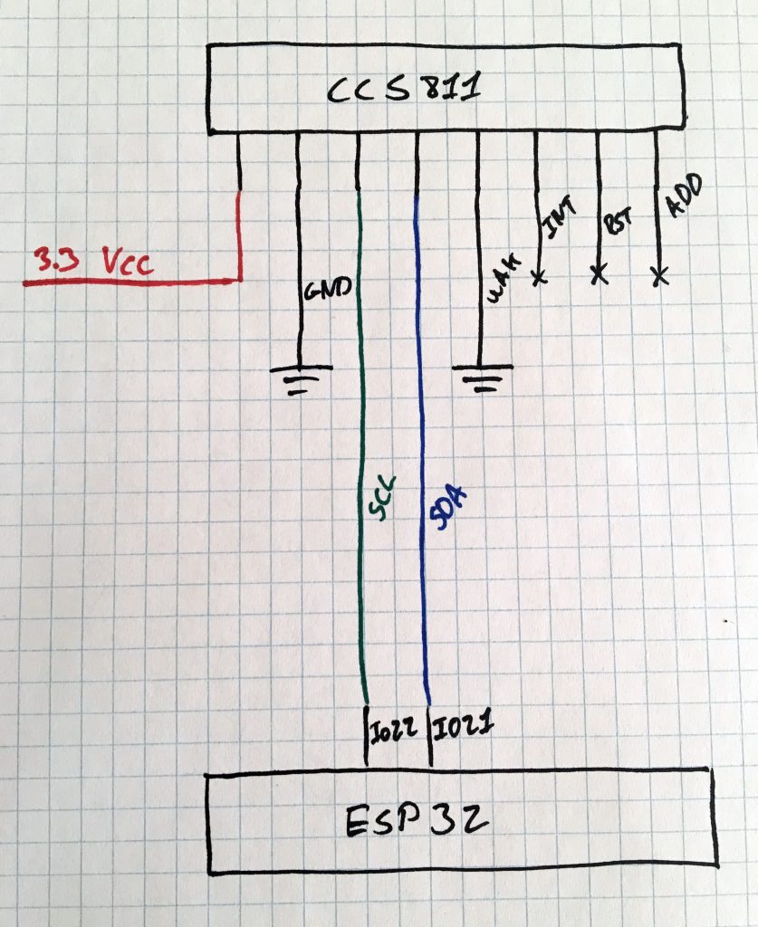
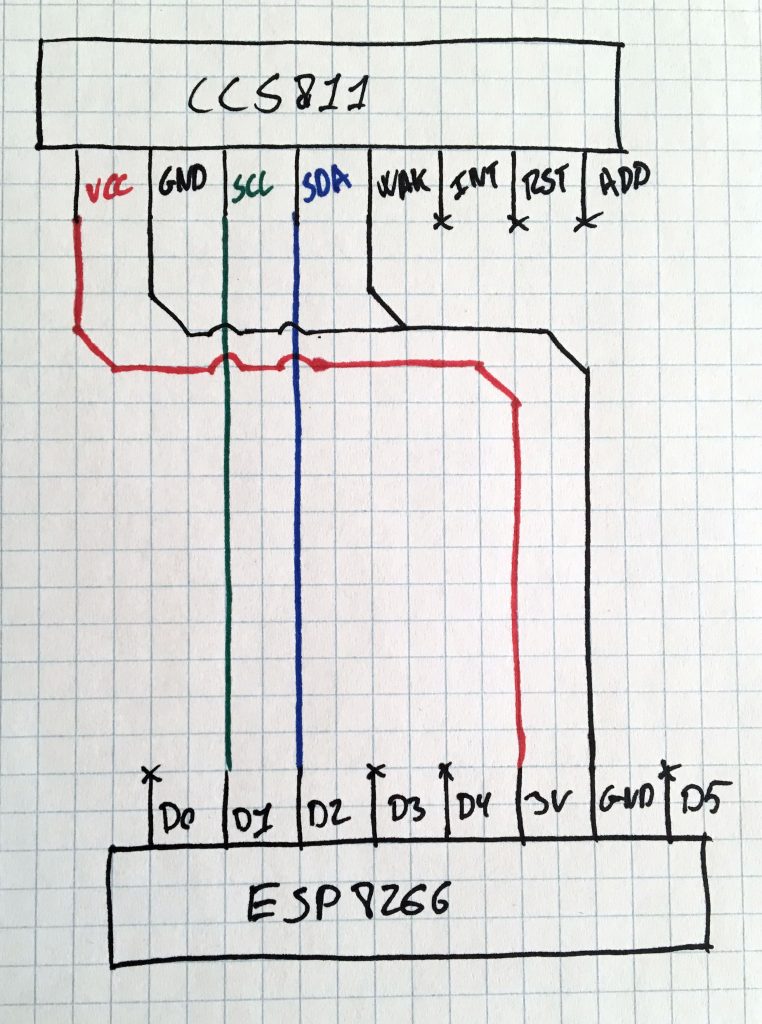
First things first – design! A few sketches on how the BME280 and the CCS811 should be wired to the ESP8266.
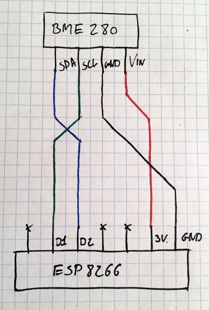
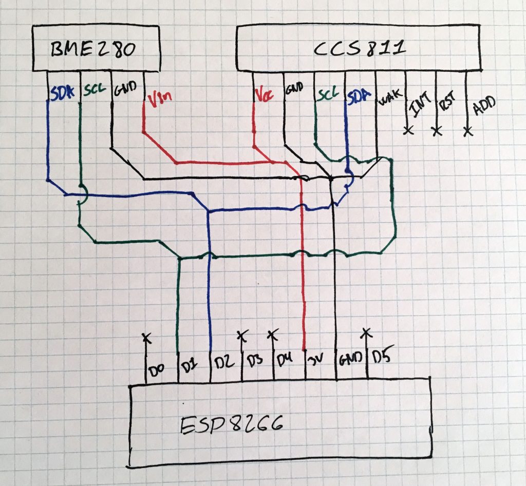
That was pretty straight forward, but I’ll do a combined one anyway of how both sensors should be wired to the ESP8266 simultaneous.
Hardware
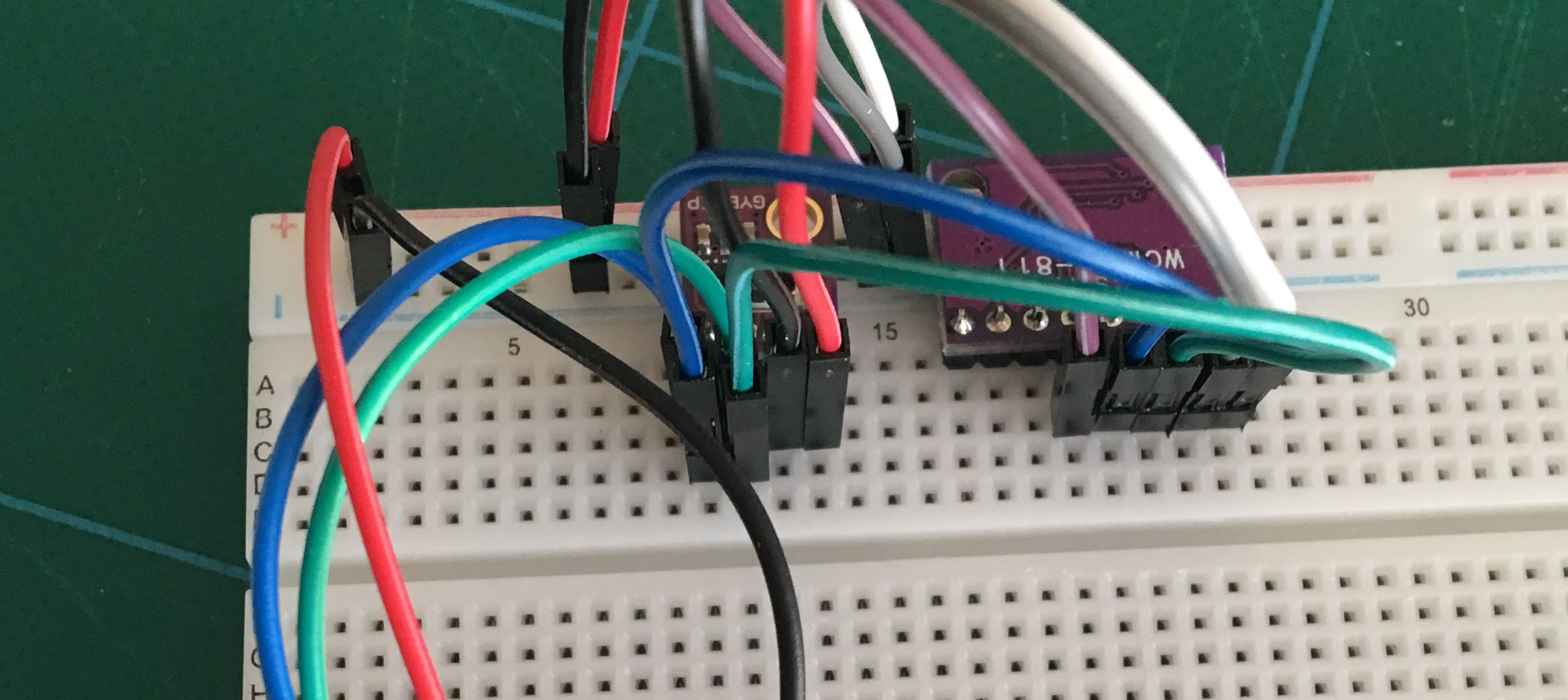
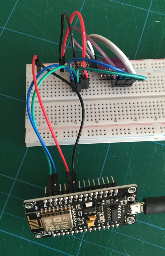
I wired it all up on a breadboard based on the diagrams to get everything up and running there. All the software development was done while I had the hardware wired on the breadboard. Only when everything was running exactly like I wanted it I soldered everything. The software is described below.
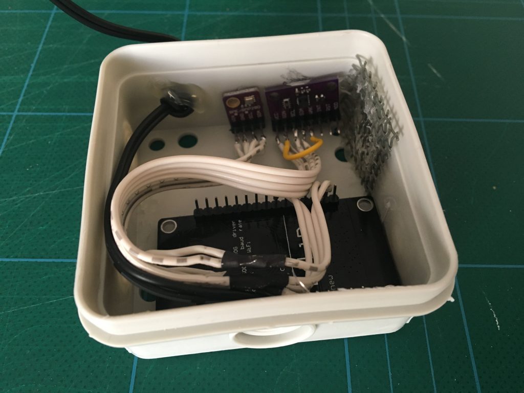
I drilled a hole in a cheap electricity junction box, which I got from the local hardware store, to allow the sensors to “sniff” the environment. To prevent spiders or others to take residence in the box I hot glued some mesh over the hole.
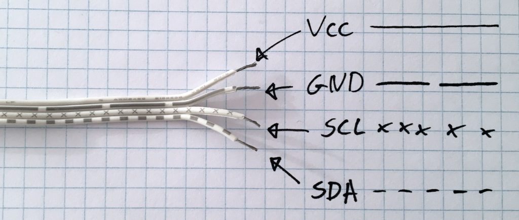
I used some ribbon cables that was in my scrap heap – this is mostly for my own reference as you will probably not have the same cable available, but this is how the wires were connected.
A 5V 600mA power supply was used and I drilled a small hole in the box for the cable. I tied a knot on the cable to ensure that the cable could not be pulled out of the box and I hot glued it as well. The wires were connected to Vin and a GND pin.
After soldering all the sensors and heat shrink tuning places in risk of shorting out I hot glued all the components into the box. The CCS811 closest the the opening as it needs better access to the outside environment to function.
Software
For the software I made a separate file for each sensor to isolate the implementations and to allow easier code sharing between sensor arrays. Both sensors has Adafruit drivers available making life a whole lot easier.
BME280 Software
The code here is pretty straight forward. Be aware of the I2C address of your particular sensor. That is set to 0x76 with bme.begin(0x76U). Pressure is less important to me than the other measurements so I’ll keep going if that one is missing. Oh yeah, and always check for NULL points – even in your own code.
#include <Arduino.h>#include <Adafruit_Sensor.h>#include <Adafruit_BME280.h>static Adafruit_BME280 bme;
/***************************************************/bool bme280_init(void) {
return bme.begin(0x76U);
}/***************************************************/bool bme280_read(float *temp, float *hum, float *pres) {
bool result = true;
if ((NULL == temp) || (NULL == hum) || (NULL == pres)) {
result = false;
}if (true == result) {
*temp = bme.readTemperature();
*hum = bme.readHumidity();
*pres = bme.readPressure() / 100.0F;
if (isnan(*hum) || isnan(*temp)) {
result = false;
}}return result;
}
CCS811 Software
The read frequency of my system is 60 seconds so I’ll setup the CCS811 sensor to this with ccs.setDriveMode(CCS811_DRIVE_MODE_60SEC). Also, that sensor will give more precise results if it is adjusted for temperature and humidity. So, if I have this data available I’ll provide it to the sensor.
Note that this sensor needs a 20 minute warm-up time before it starts giving measurements. This is also why I dropped putting the ESP8266 in Deep Sleep mode in between readings. The sensor would start a new warm-up after every wake up after a Deep Sleep resulting in data never being available from this sensor. This could be solved by not powering the sensor from the ESP8266. I might explore this further sometime in the future.
#include <Arduino.h>#include <Adafruit_CCS811.h>static Adafruit_CCS811 ccs;
/***************************************************/bool ccs811_init(void) {
bool result = true;
if (ccs.begin()) {
ccs.setDriveMode(CCS811_DRIVE_MODE_60SEC);
} else {
result = false;
}return result;
}/***************************************************/bool ccs811_read(uint16_t* eCO2, uint16_t* tvoc, float temp, float hum) {
bool result = true;
if ((NULL == eCO2) || (NULL == tvoc)) {
result = false;
}if (true == result) {
result = false;
if (!isnan(temp) && !isnan(hum)) {
ccs.setEnvironmentalData((uint8_t)hum, (double)temp);
}if (0U == ccs.readData()) {
uint16_t tempCo2 = ccs.geteCO2();
uint16_t tempTvoc = ccs.getTVOC();
if ((tempCo2 + tempTvoc) > 0U) {
*eCO2 = tempCo2;
*tvoc = tempTvoc;
result = true;
}}}return result;
}
Publisher Software
I created a module for handling publishing of data which also handles WiFi connection. In the code below insert your own SSID and WiFi password. To connect to an InfluxDB like the one described in Collect, Present, Alert then make sure to change the IP address and port number to where your server is running.
Note that line two should be #include <WiFi.h> if running on an ESP32.
#include <Arduino.h>#include <ESP8266WiFi.h>#include <WiFiUDP.h>// WiFi credentials.WiFiUDP udp;const char* WIFI_SSID = "<YOUR SSID>";
const char* WIFI_PASS = "<YOUR PASSWORD>";
// IP address and port of InfluxDBbyte DB_HOST[] = {192U, 168U, 0U, 1U};
int DB_DATA_PORT = 65000U;
/***************************************************/bool publisher_init(void) {
bool result = true;
uint8_t retries = 0U;
WiFi.mode(WIFI_STA);
WiFi.disconnect();
delay(100U);
WiFi.begin(WIFI_SSID, WIFI_PASS);
while ((WiFi.status() != WL_CONNECTED) && (retries < 10U)) {
result = false;
if (WiFi.status() == WL_CONNECT_FAILED) {
Serial.println("ERROR: Failed to connect to WIFI.");
}retries++;
delay(2000U);
}if (WiFi.status() == WL_CONNECTED) {
result = true;
Serial.print("INFO: IP address: ");
Serial.println(WiFi.localIP());
}return result;
}/***************************************************/bool publisher_sendData(String data) {
bool result = true;
if (WiFi.status() != WL_CONNECTED) {
result = publisher_init();
}if (true == result) {
udp.beginPacket(DB_HOST, DB_DATA_PORT);
udp.print(data);
udp.endPacket();
}return result;
}
main.cpp Software
The two sensor softwares just presented will be used for the main program. Measurements will be stored in an InfluxDB as described in Collect, Present, Alert. Therefore, the sensor reading as stored in a string called line as InfluxDB Line Protocol.
The format of the InfluxDB Line Protocol is in short:
- The name of the measurement.
- A tag which in this case is location as I’ll collect the same kind of measurements from different locations.
- A field called value which holds the measured value.
/***************************************************//********************** SETUP **********************//***************************************************/void setup()
{/* Setup serial communication. */Serial.begin(9600U);
delay(1000U);
/* Perform initializations. */if (!publisher_init()) {
Serial.println("ALARM: Failed to start publisher - check WiFi.");
while (1);
}if (!bme280_init()) {
Serial.println("CRITICAL: Failed to start BME280 temp/hum/bar sensor - check wiring.");
while (1);
}if ( !ccs811_init() ) {
Serial.println("CRITICAL: Failed to start CCS811 CO2/TVOC sensor - check wiring.");
while(1);
}}/***************************************************//********************** LOOP *********************//***************************************************/void loop()
{String line = "";
float temp = NAN;
float hum = NAN;
float pres = NAN;
if (bme280_read(&temp, &hum, &pres)) {
line = String(line + "temperature,location=upstairs value=" + String(temp) + "\n");
line = String(line + "humidity,location=upstairs value=" + String(hum) + "\n");
line = String(line + "pressure,location=upstairs value=" + String(pres) + "\n");
}uint16_t eCO2 = 0U;
uint16_t tvoc = 0U;
if (ccs811_read(&eCO2, &tvoc, temp, hum)) {
line = String(line + "carbondioxid,location=upstairs value=" + String(eCO2) + "\n");
line = String(line + "tvoc,location=upstairs value=" + String(tvoc) + "\n");
}if (line != "") {
Serial.println(line);
publisher_sendData(line);
}// Now waitdelay(60000U);
}
Conclusion
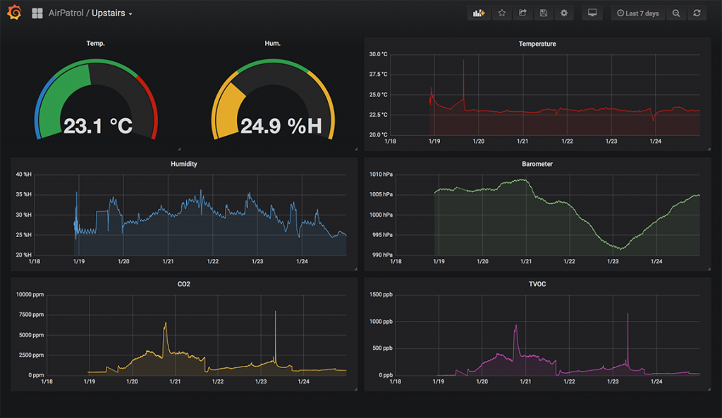
With the sensor in place and the software running my data started ticking is as expected. Then this was the result in Grafana after a bit of setup.
With regards to future expansions I might look into possible Deep Sleep options with the CCS811 sensor so I can save a bit of power.
ESP32 Bonus
If you’re using an ESP32 instead of an ESP8266 then these wiring diagram will work along with the same software as above.