
This build consists of an ESP32 with a PMS5003 particle sensor, a BME280 temperature sensor, and a MICS6814 gas sensor for environment monitoring. This is the second sensor array in the system I call AirPatrol. For reasons I explained previously I call this sensor array Marshall. It will monitor environment conditions in my living room. This sensor array looks a lot like Chase and some of the building blocks are the same. Therefore, these building blocks will not be described in as much detail in this post. I will, however, make sure to drop links whenever appropriate.
Materials
Let me start out with a few words on the choices of components before presenting lists of materials and tools used.
PMS5003 is a particle sensor. It uses laser to measure the concentration of particles – PM1.0, PM2.5, and PM10.0. These represent particles of sizes 0.3-1.0, 1.0-2.5, and 2.5-10 μm respectively. The sensor uses a fan to circulate the air. This fan must run for 30-60 seconds before measurements are reliable. The laser diode in this sensor has a lifetime of 8000 hours. Thus, I need to take measures to ensure the sensor doesn’t ware out in about a year.
The BME280 temperature, humidity, and pressure sensor was also used for Chase. I’m happy with that sensor and will use it again for this build.
I’m not satisfied with the CCS811 gas sensor I used for Chase. As a consequence I’ve been on the look-out for alternatives. The choice fell on the MICS6814 which measures carbon monoxide, nitrogen dioxide, and ammonia. As opposed to the other sensors this one is analog.
Which leads me to the choice of main board. The ESP32 has more ADC-pins than the ESP8266. And since the MICS6814 has three analog output pins the natural choice is the ESP32.
Materials:
- ESP32 Main board.
- PMS5003 Particle sensor.
- BME280 Temperature, Humidity, and Pressure sensor.
- MICS6814 Gas sensor.
- Veroboard.
- Resistors.
- 2 x 10kΩ
- 3 x 47kΩ
- 5V Power Supply.
- Plastic box.
- Wires.
- Heat shrink tube.
Tools:
- Wire cutters.
- Soldering iron.
- Hot glue gun.
Optional:
Design
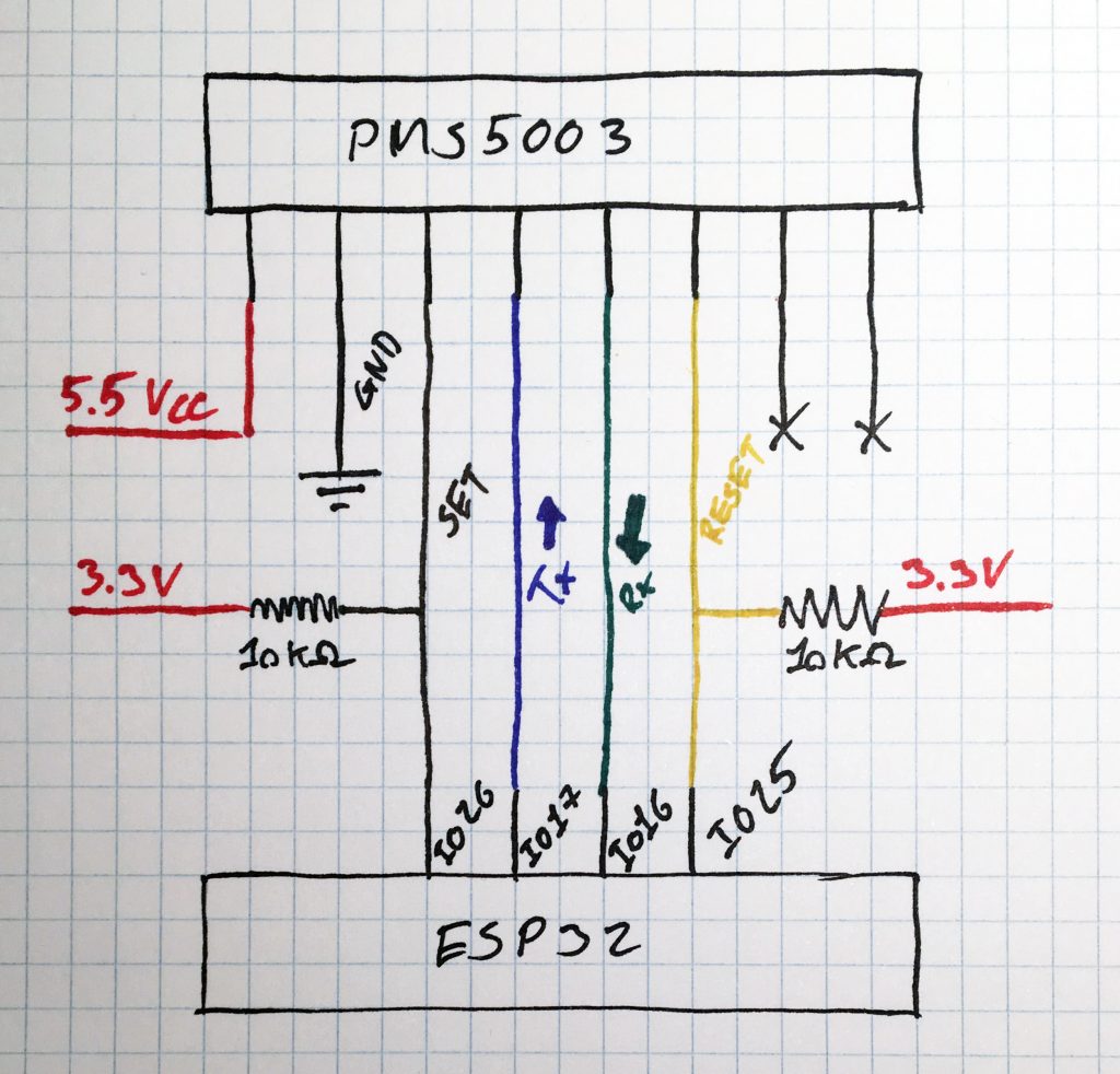
A few design sketches has never hurt anyone. First PMS5003 wiring to the ESP32. I followed wiring diagram from the PMS5003 specification. Note that the sensor requires 5V to operate, while the signalling is 3.3V.
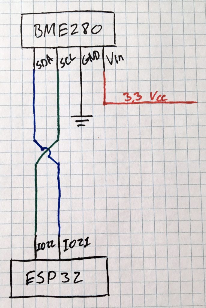
Then wiring of BME280 to ESP32 – which was also presented for Chase.
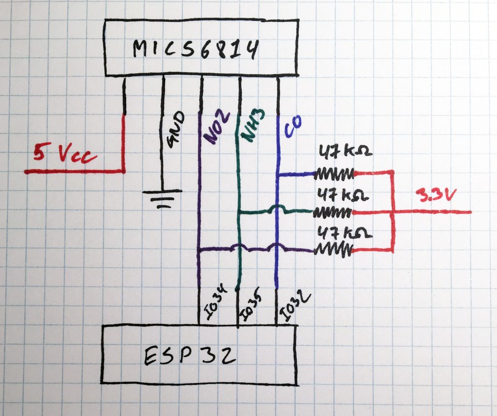
Finally, the wiring of MICS6814 to ESP32. Like with the PMS5003 this sensor requires 5V supply while the analog signals max out at 3.3V.
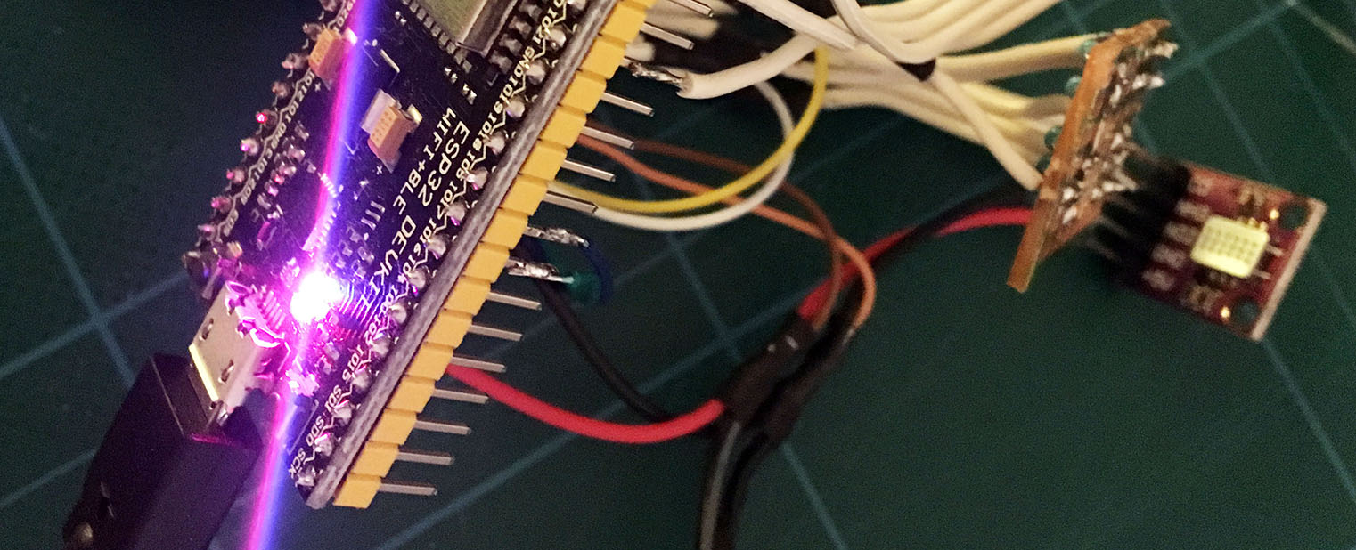
Hardware
Some of the sensors were tricky to get working. Here are some of the details.
PMS5003
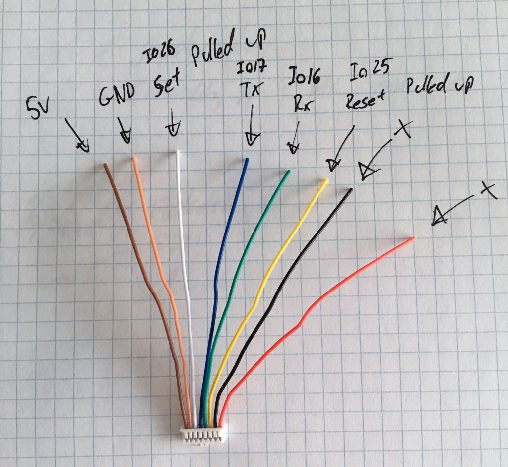
First off an overview of the colour coding of the PMS5003 connector wires. These colours vary from sensor to sensor so make sure to double check your own.
I had the sensor wired up and running on a breadboard for a while before doing the assembly. As mentioned earlier this sensor wears out after 8000 hours of operation. Pulling the set pin low will disable the sensor. My idea was to keep the set pin low for 9-10 minutes, pull it high and let it run for one minute and then do my measurements. The rest of the system measures every minute.
In the beginning I did get measurements, but not as expected. The sensor has two modes: Active mode and Passive mode. The default mode is Active and the sensor automatically sends readings every second or so. In Passive mode a command is sent to the sensor which then transmits one reading.
My intention was for the operation sequence to be like this for start up:
- Power on sensor.
- Put sensor in Passive mode.
And for this when it was running:
- Wait one minute.
- Request data.
- Read Rx pin until data received.
- Pull SET pin low.
- Wait 9 minutes.
- Pull SET pin high.
- Repeat from the top of the list.
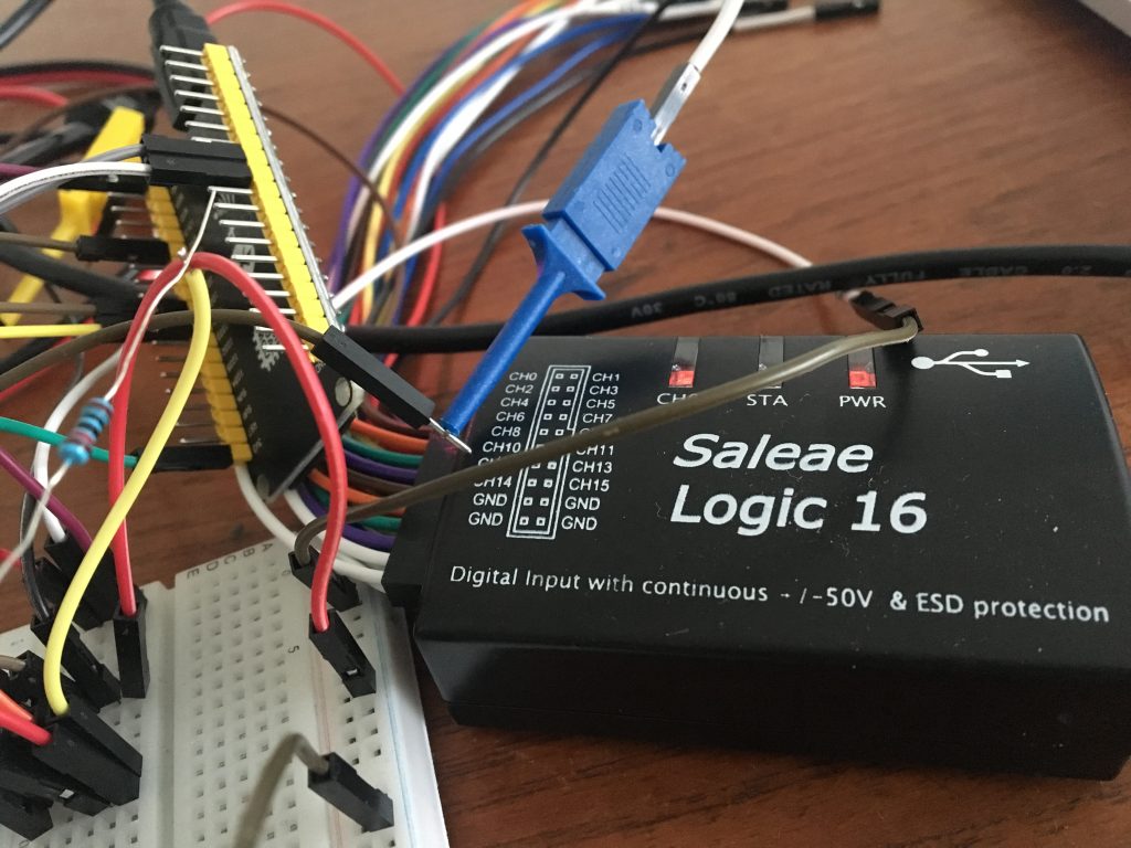
With this setup I frequently experienced data not available on the Rx pin – which was running with a one second timeout. It was time to put my Saleae Logic 16 logic analyser to work. A logic analyser is a debug tool that makes it possible to “listen in” on the traffic on the wires.
Unfortunately, I didn’t take the appropriate screenshots during the process. But these are my finding.
In the first iteration I didn’t have the ESP32 Tx pin wired up correctly, so the PMS5003 didn’t receive my commands. It would stay in active mode and transmit data every second. My read timeout being one second sometimes due to timing I would not receive all the data before timing out. Doubling my timeout value made the issue of data not available go away.
Second iteration it did receive my commands and the first attempt to read data did go as expected: passive mode, request data, read data, set pin low. But when the set pin was pulled high again the sensor would have cleared the passive mode setting and gone back to active mode. I tried putting it back into passive mode right after pulling the set pin high, but the sensor ignored commands at this point. It probably needs a bit of time before being ready. But at this point I reached the conclusion:
If it ain’t broken, then don’t fix it.
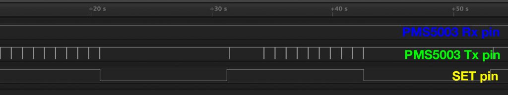
I did get data from the sensor. I did put it to sleep between readings to extend it’s lifetime. Active mode would work just fine for me. Below are the final trace of data on the wire. The sleep and active periods are reduced in the trace for debugging purpose.
MICS6814
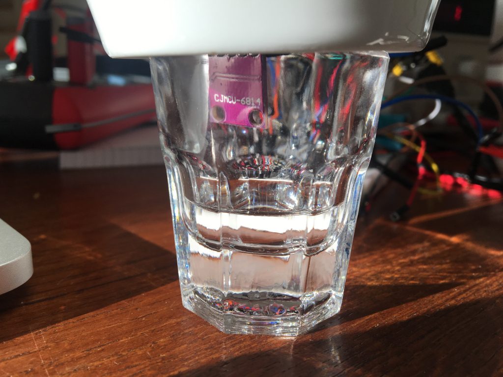
During the build process I needed to test the MICS6814. First I connected the sensor directly to a power supply and a voltmeter to test the readings. I used a small glass with ethanol to test the sensor.
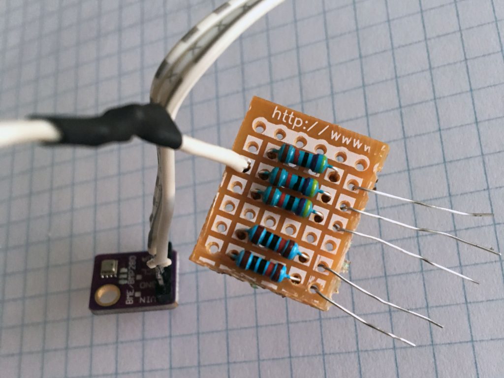
The MICS6814 is an analog gas sensor, so it needs pull up resistors to give valid readings. Took me a while and some frustration to get right. The ADC on the ESP32 will convert 0-3.3V to digital values. Therefore, I needed to make sure the readings were inside this range. I did this through the values of the resistors. I mounted all the pull up resistors for this build on the same piece of veroboard.
When I had that working I wired the sensor up on a breadboard before final assembly and soldering.
Final assembly
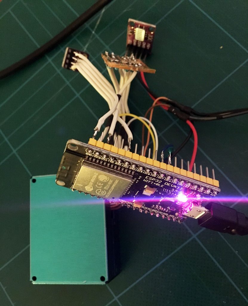
After getting everything running on a breadboard I soldered everything together.
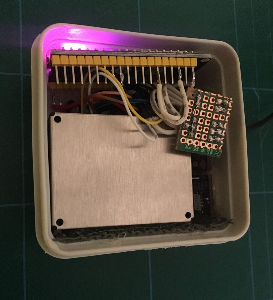
Double checked that everything was working after assembly. And the finally mounted it all in a box. I had cut a venting hole in the bottom of the box to allow both PMS5003 and MICS6814 access to fresh air. The hole is covered with a mesh to prevent spiders and similar to move into the box.
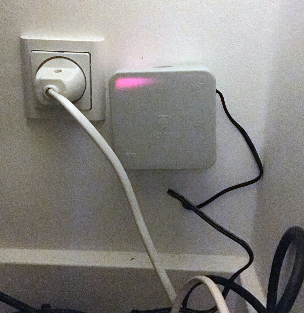
Sensor box temporarily mounted on the wall in the corner of the living room.
Software
The software makes use of components I already had from Chase. For software for the BME280 sensor and for the data publisher, see ESP8266, BME280, CCS811 Sensor Build.
PMS5003 Software
A few libraries exist for controlling the PMS5003. I downloaded a few and played around with them. I ended up using the fu-hsi/pms library. The sensor is reset if data cannot be read from it. As mentioned earlier the sensor will run for one “tick” before doing a reading. Then it will sleep for nine “ticks” before repeating. In my system a tick is one minute.
#include <Arduino.h>#include "PMS.h"#define PMS_SET_PIN 26U#define PMS_RST_PIN 25U#define PMS_READ_INTERVAL 9U#define PMS_READ_DELAY 1Uuint8_t pms_tick_count = PMS_READ_INTERVAL;
PMS pms(Serial2);
/***************************************************/static void setup_pins(void) {
pinMode(PMS_RST_PIN, OUTPUT);
digitalWrite(PMS_RST_PIN, HIGH);
pinMode(PMS_SET_PIN, OUTPUT);
digitalWrite(PMS_SET_PIN, HIGH);
}/***************************************************/static void toggle_set(bool sleep) {
if (sleep) {
digitalWrite(PMS_SET_PIN, LOW);
} else {
digitalWrite(PMS_SET_PIN, HIGH);
}delay(500U);
}/***************************************************/static void toggle_reset(void) {
digitalWrite(PMS_RST_PIN, LOW);
delay(500U);
digitalWrite(PMS_RST_PIN, HIGH);
delay(500U);
}/***************************************************/bool pms5003_init(void) {
setup_pins();
Serial2.begin(PMS::BAUD_RATE, SERIAL_8N1, 16U, 17U);
delay(1000U);
pms_tick_count = PMS_READ_INTERVAL;
return true;
}/***************************************************/bool pms5003_read(uint16_t *pmSp1_0, uint16_t *pmSp2_5, uint16_t *pmSp10_0,
uint16_t *pmAe1_0, uint16_t *pmAe2_5, uint16_t *pmAe10_0) {
bool result = false;
if ((NULL == pmSp1_0) || (NULL == pmSp2_5) || (NULL == pmSp10_0)
|| (NULL == pmAe1_0) || (NULL == pmAe2_5) || (NULL == pmAe10_0)) {
result = false;
}else {
pms_tick_count++;
if (pms_tick_count == PMS_READ_DELAY) {
PMS::DATA data;
while (Serial2.available())
{Serial2.read();
}if (pms.readUntil(data, 2U*PMS::SINGLE_RESPONSE_TIME))
{*pmSp1_0 = data.PM_AE_UG_1_0;
*pmSp2_5 = data.PM_AE_UG_2_5;
*pmSp10_0 = data.PM_AE_UG_10_0;
*pmAe1_0 = data.PM_SP_UG_1_0;
*pmAe2_5 = data.PM_SP_UG_2_5;
*pmAe1_0 = data.PM_SP_UG_10_0;
result = true;
}else{toggle_reset();
}toggle_set(true);
} else if (pms_tick_count >= PMS_READ_INTERVAL) {
toggle_set(false);
pms_tick_count = 0U;
}}return result;
}
MICS6814 Software
Analog reading are prone to noise. To mitigate this I average three readings from each pin for the final results. Like with the CCS811 this sensor has a warm up period before readings are accurate. Don’t trust the readings for the first 20 minutes or so. There is no guard for this in the software.
#include <Arduino.h>#include <driver/adc.h>#define ADC_MAX_VALUE 4095U#define ADC_MIN_VALUE 0U#define ADC_SAMPLES 3U#define ADC_SAMPLE_DELAY 100U/***************************************************/bool mics6814_init(void) {
adc1_config_width(ADC_WIDTH_BIT_12);
adc1_config_channel_atten(ADC1_CHANNEL_6, ADC_ATTEN_DB_11);
adc1_config_channel_atten(ADC1_CHANNEL_7, ADC_ATTEN_DB_11);
adc1_config_channel_atten(ADC1_CHANNEL_4, ADC_ATTEN_DB_11);
return true;
}/***************************************************/bool mics6814_read(uint16_t* no2, uint16_t* nh3, uint16_t* co) {
bool result = true;
if ((NULL == no2) || (NULL == nh3) || (NULL == co)) {
result = false;
}uint16_t tempNo2 = 0U;
uint16_t tempNh3 = 0U;
uint16_t tempCo = 0U;
uint8_t count = 0U;
while ((true == result) && (count < ADC_SAMPLES)) {
if (count > 0U) {
delay(ADC_SAMPLE_DELAY);
}int temp = adc1_get_raw(ADC1_CHANNEL_6);
if ((temp >= ADC_MIN_VALUE) && (temp <= ADC_MAX_VALUE)) {
tempNo2 += (uint16_t)temp;
} else {
result = false;
}if (true == result) {
temp = adc1_get_raw(ADC1_CHANNEL_7);
if ((temp >= ADC_MIN_VALUE) && (temp <= ADC_MAX_VALUE)) {
tempNh3 += (uint16_t)temp;
} else {
result = false;
}}if (true == result) {
temp = adc1_get_raw(ADC1_CHANNEL_4);
if ((temp >= ADC_MIN_VALUE) && (temp <= ADC_MAX_VALUE)) {
tempCo += (uint16_t)temp;
count++;
} else {
result = false;
}}}if (true == result) {
*no2 = ADC_MAX_VALUE - (tempNo2 / ADC_SAMPLES);
*nh3 = ADC_MAX_VALUE - (tempNh3 / ADC_SAMPLES);
*co = ADC_MAX_VALUE - (tempCo / ADC_SAMPLES);
}return result;
}
main.cpp Software
The main program will consist of the two sensor softwares just presented and of the BME280 and Publisher softwares from Chase.
Measurements will be stored in an InfluxDB as described in Collect, Present, Alert. Therefore, the sensor reading as stored in a string called line as InfluxDB Line Protocol.
The format of the InfluxDB Line Protocol is in short:
- The name of the measurement.
- A tag which in this case is location as I’ll collect the same kind of measurements from different locations.
- A field called value which holds the measured value.
/***************************************************//********************** SETUP **********************//***************************************************/void setup()
{/* Setup serial communication. */Serial.begin(9600U);
delay(1000U);
/* Perform initialisations. */if (!publisher_init()) {
publisher_sendSyslog(SYSLOG_ALARM, "Failed to start publisher - check WiFi.");
while (1);
}if (!bme280_init()) {
publisher_sendSyslog(SYSLOG_CRITICAL, "Failed to start BME280 temp/hum/bar sensor - check wiring.");
while (1);
}if ( !pms5003_init() ) {
publisher_sendSyslog(SYSLOG_CRITICAL, "Failed to start PMS5003 particle sensor - check wiring.");
while(1);
}if ( !mics6814_init() ) {
publisher_sendSyslog(SYSLOG_CRITICAL, "Failed to start MICS6814 gas sensor - check wiring.");
while(1);
}publisher_sendSyslog(SYSLOG_DEBUG, "Setup successful.");
}/***************************************************//********************** LOOP *********************//***************************************************/void loop() {
String line = "";
float temp = NAN;
float hum = NAN;
float pres = NAN;
if (bme280_read(&temp, &hum, &pres)) {
line = String(line + "temperature,location=" + String(LOCATION) + " value=" + String(temp) + "\n");
line = String(line + "humidity,location=" + String(LOCATION) + " value=" + String(hum) + "\n");
line = String(line + "pressure,location=" + String(LOCATION) + " value=" + String(pres) + "\n");
}uint16_t pmSp1_0 = 0U;
uint16_t pmSp2_5 = 0U;
uint16_t pmSp10_0 = 0U;
uint16_t pmAe1_0 = 0U;
uint16_t pmAe2_5 = 0U;
uint16_t pmAe10_0 = 0U;
if (pms5003_read(&pmSp1_0, &pmSp2_5, &pmSp10_0, &pmAe1_0, &pmAe2_5, &pmAe10_0)) {
line = String(line + "particle,location=" + String(LOCATION) + " pm_ae_1_0=" + String(pmSp1_0) + ",pm_ae_2_5=" + String(pmSp2_5) + ",pm_ae_10_0=" + String(pmSp10_0) + ",pm_sp_1_0=" + String(pmAe1_0) + ",pm_sp_2_5=" + String(pmAe2_5) + ",pm_sp_10_0=" + String(pmAe10_0) + "\n");
}uint16_t no2 = 0U;
uint16_t nh3 = 0U;
uint16_t co = 0U;
if (mics6814_read(&no2, &nh3, &co)) {
line = String(line + "gas,location=" + String(LOCATION) + " no2=" + String(no2) + ",nh3=" + String(nh3) + ",co=" + String(co) + "\n");
}if (line != "") {
Serial.println(line);
publisher_sendData(line);
} else {
publisher_sendSyslog(SYSLOG_INFO, "Nothing to transmitted.");
}// Now sleepdelay(60000U);
}
Conclusion
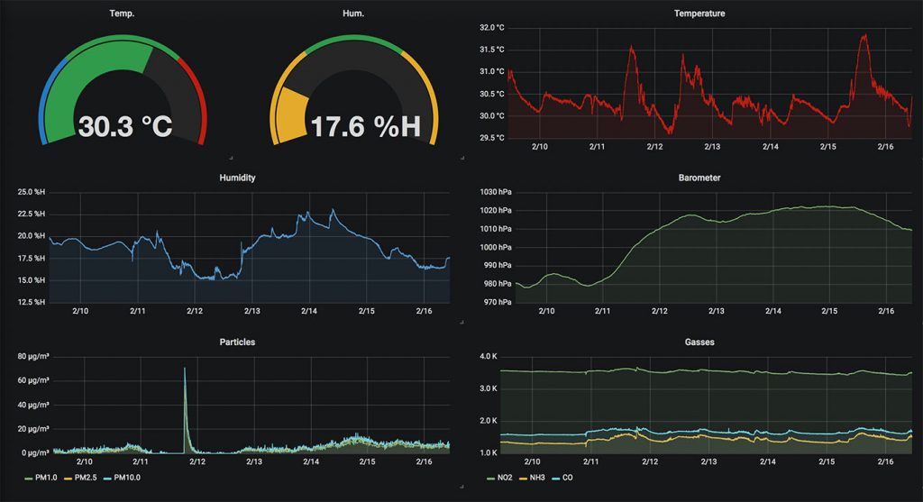
With everything up and running and a new dashboard setup in Grafana the sensor build was done.
Evaluation
After the sensor array was done I was quick to mount it in the corner of the living room – close to the floor.
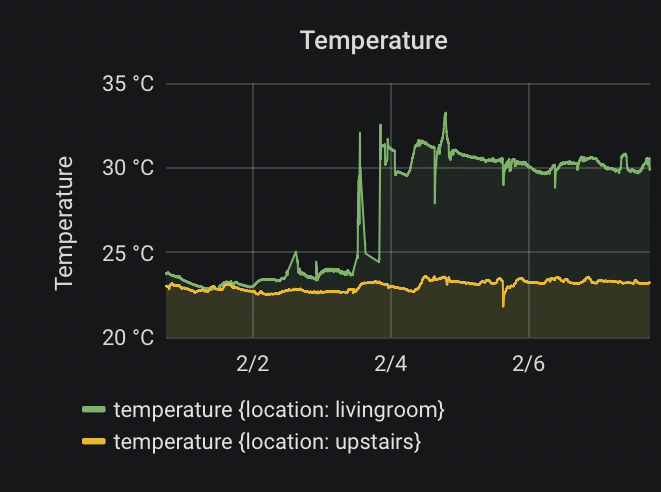
As the data started to tick in I noticed a higher temperature and a lower humidity than I had seen before. I blamed the location and tried moving to where I had it during the build and testing. Same results. Even removing the lid did not lower the temperature.
The graph below show the result before and after the build was done. And with Chase as a reference. A temperature increase of 6-8 degrees Celsius.
I had noticed MICS6814 could get warm, so I decided to take a thermal image of the setup. Sure enough, MICS6814 is heating everything around it.
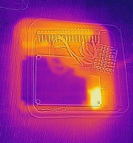
Haven’t we all lived in an apartment with a noisy neighbour? Well, this is just too much and the neighbour has to go. I need to find another gas sensor, that does not disturb the temperature readings. I’m thinking BME680 but that will be the topic of another post.